 ISSN: 2822-0838 Online

Development of a Battery-operated Plasma Device Using Dielectric Barrier Discharge Plasma in Ambient Air
Khoi Nguyen Ho and Anirut Chaijaruwanich*Published Date : 2018-01-01
DOI : https://doi.org/10.12982/CMUJNS.2018.0005
Journal Issues : Number 1 , January-March 2018
ABSTRACT
Dielectric barrier discharge (DBD) plasma in air, a kind of non-thermal plasma, can disinfect the surface of a wound and enhance blood clotting without tissue damage. The purpose of this study was to design a prototype of a new, easily portable, DBD plasma device for first aid. In our prototype, the plasma discharge could be adjusted by changing frequency and using the pulse width modulation (PWM) function from a microcontroller. An electrode, coupled with the surface micro discharge (SMD) technique, reduced current leakage passing through the body. While the Lissajous standard method was utilized to measure the energy consumption per cycle, the optical emission spectroscopy approach analyzed the elements of plasma generation in ambient air. The prototype was convenient to carry and the amount of plasma discharge (containing the activated species O, OH, O2-,
O3, N2, N2+) was easily varied to affect microorganisms and tissue.
Keywords: Battery-operated plasma device, Dielectric barrier discharge, Non-thermal plasma, Plasma discharge in air
INTRODUCTION
High voltage in the gap between two plane-parallel metal electrodes, in which at least one of them is covered by a dielectric layer, produces DBD plasma (Figure 1) (Priyadarshini, 2013). The dielectric barrier is made of a material of low dielectric loss and high dielectric strength: such as glass, quartz, or ceramics (Fridman and Friedman, 2013). To ignite plasma between the electrodes, the electric field across the two electrodes must be high enough to cause dielectric breakdown of the gases in ambient air. The minimum breakdown voltage calculated from the Townsend avalanche and the Paschen curve is about 3 kV/mm (Lieberman and Lichtenberg, 2015). DBD plasma is a relatively novel technology, environmentally friendly, and safe for humans. Previous studies have shown that it could be used directly on human tissue without damage or pain (Fridman et al., 2006). DBD plasma in air has been shown to effectively reduce wound healing time through many factors, including clotting, decontamination, anti-inflammatory, and healing processes (Fridman and Friedman, 2013). This has allowed for development of devices for treating wounds in a hospital, on a battlefield, and at home. Many kinds of non-thermal plasma devices already exist for healthcare and laboratory use. However, few multi-functional devices are truly mobile. For example, PlasmaDerm VU-2010 (CINOGY GmbH Duderstadt, Germany), a commercial plasma device for treating wounds, must be powered by an external power source and, therefore, has limited mobility. Likewise, a battery-operated atmospheric-pressure plasma wand (Pei et al., 2014) and a solar powered handheld plasma device (Ni et al., 2016), although mobile, operate at a single frequency only; in addition, their sizes are inconvenient to carry and their batteries require cannot be recharged by a 5-V mobile phone charger.
The production of plasma discharge depends on the behavior of electrons, which can be modified by adjusting the voltage and frequency of electric current. While the electron temperature depends on the potential between the electrodes, the electron density is influenced by the excitation frequency (Keida and Beilis, 2013). The voltage-current relationship and the mean-power consumption of plasma discharge can represent the differences between plasma discharges. The surface micro discharge (SMD) technique, a grounded mesh electrode embedded on the outer surface of the dielectric-covered high voltage electrode, reduces the micro current passing though the body (Li et al., 2012). This technique also aids in the design of larger and more flexible plasma electrodes, as plasma is generated in multiple microdischarges around each line of the grounded mesh electrode (Isbary et al., 2013). Emmert et al. (2013) demonstrated that the typical species in air-plasma, including reactive oxygen species (O, OH, O2-, and O3) and reactive nitrogen species (N2, N2+), play a part in enhancing wound healing. Hence, optical emission spectroscopy (OES), a method to analyze the wavelengths of photons emitted by atoms or molecules during their transition, is necessary to determine the composition of plasma discharge (Keida and Beilis, 2013).
The goal of this study was to produce a prototype of a new DBD plasma device that could control the production of plasma discharge for a variety of plasma treatments and could be powered by 3.7 V Lithium-ion batteries to enhance portability.
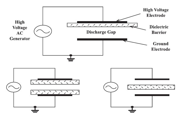
Figure 1. Principle of DBD plasma (Priyadarshini, 2013).
MATERIALS AND METHODS
Electrical design
As our prototype device was designed to be powered by a 3.7 V Lithium ion battery, the voltage must be stepped-up in three steps (Figure 2). The first boosts the voltage from about 3.7 to 12 V DC and the second amplifies the pulse signal from 5 to 12 V DC before going to the high-voltage transformer. The last step increases the amplitude of the pulse signal through a high-voltage transformer to get an alternating high-voltage output. The high-voltage transformer is a fly-back transformer operating at a frequency of about 15-40 kHz. Additionally, the design used an Atmega168A microcontroller to generate a controlled pulse signal that could be varied effortlessly along a wide range of frequencies (1 Hz - 1 MHz). The microcontroller can adjust the energy for each cycle of pulse signal, owing to the function of pulse width modulation (PWM), a well-known technique for controlling analog circuits with a microcontroller’s digital outputs (Barr, 2001). Repeating a series of on-off pulses regulates the voltage or current supplied to the analog load. For each cycle, the longer the circuit is turned on, the more power it gains; the percentage of ‘on-time’ is represented by the duty-cycle value. Using the PWM technique, the amplitude of the high-voltage output is easily varied.
An LCD block and buttons allow the user to control the device; a 5-V regulator circuit supplies power to this and the microcontroller block (Figure 2). The gate driver circuit uses a TLP 250 photocoupler to isolate the low voltage area from the high voltage area, preventing damage to the circuit. Likewise, a Snubber protection circuit is placed across the Mosfet semiconductor component; this provides protection and improved performance (Marty, 1990). The Lithium batteries are protected from overload or overcharging by a battery-charging protector circuit and a microcontroller that detects the battery charge level.
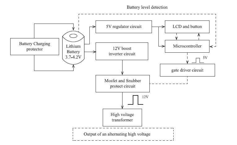
Figure 2. Block diagram of the overall system.
Note: The solid arrows trace the power supply and the dashed arrows trace the controlling signal.
Electrode and cover design
The electrode of the prototype device is an indirect plasma electrode that uses SMD technique. It consists of a planar core, a dielectric barrier, a mesh, and a cover (Figure 3). The planar core is made of copper (55×17×0.2 mm), the dielectric barrier is made of borosilicate glass (60×22×1 mm), the mesh is made of stainless steel, and the cover is made of polylactic acid (PLA). The Inventor program was used to design the size and shape of the electrode (70×30×20 mm). Additionally, the body of the device was designed to be comfortable to hold. The models were built with a Makerbot Replicatior+ 3D printer using PLA filament.

Figure 3. 3D model of the electrode.
Programming
A program was created for the Atmega168A microcontroller to detect the battery charge level and provide the user interface. The flow chart in Figure 4 shows the program’s algorithm.
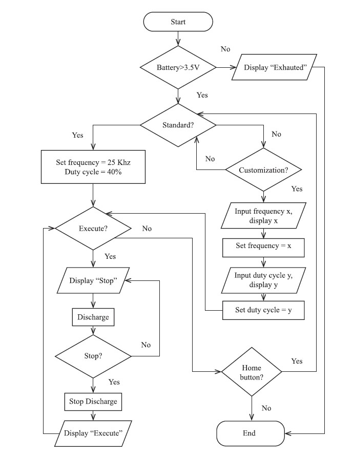
Figure 4. Flow chart of the program algorithm.
Measurement methods
Electrical characterization. The high-voltage output was measured by a high-voltage probe (FLUKE model, maximum 40 kV); the current waveforms were recorded by measuring the voltage across a 100 Ω resistor connected in series with the electrode (Figure 5). To measure the discharge at the electrode, the resistor was replaced by a 3-nF capacitor. The discharge energy per cycle was calculated based on the area of the charge-voltage Lissajous figure (Kostov et al., 2010). The mean power consumption was calculated by multiplying the energy of each cycle by the source frequency (Mahoney et al., 2010). The charge-voltage Lissajous figure is a standard method for the electrical diagnostics of DBD discharges (Jiang et al., 2013). All results were recorded by Agilent InfiniiVision DSO-X-2002A oscilloscopes.
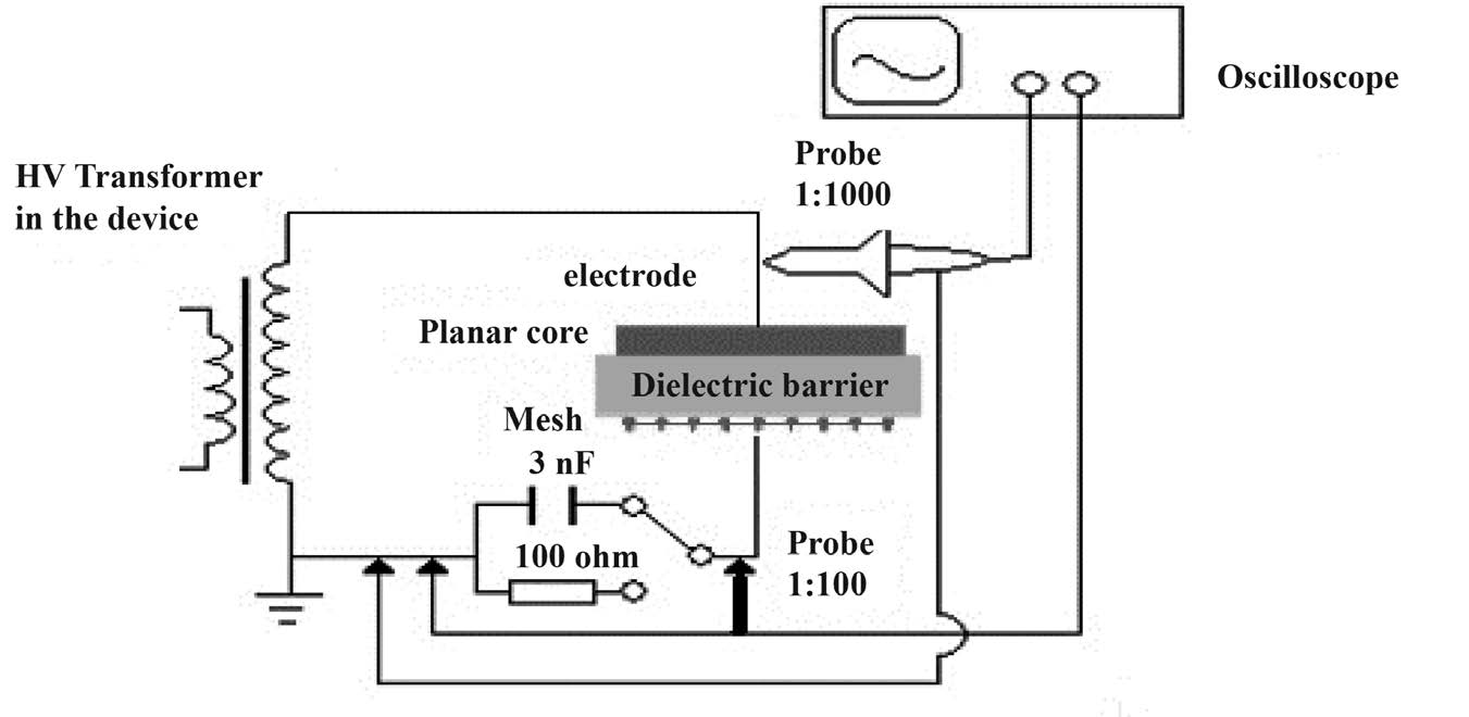
Figure 5. Diagram of the electrical experiment setup.
Optical Emission Spectroscopy (OES). Each particle species in plasma emits a characteristic set of discrete wavelengths, depending on its electronic structure; thus, collecting wavelength data can help determine the plasma composition. The wavelengths of photons emitted by atoms or molecules during their transition can be inspected by optical emission spectroscopy (Keida and Beilis, 2013). This study used an AvaSpec-2048 photometer that was calibrated by a wavelength generator from Ocean Optics.
RESULTS
Prototype of device
The size of the prototype device was 150×70×30 mm; it weighed 200 grams. The user controlled the prototype through a multifunctional rotary button, and received feedback via an LCD display (Figure 6). The battery was recharged using an android phone charger. Given these characteristics, the prototype was mobile, convenient, and easy to handle.
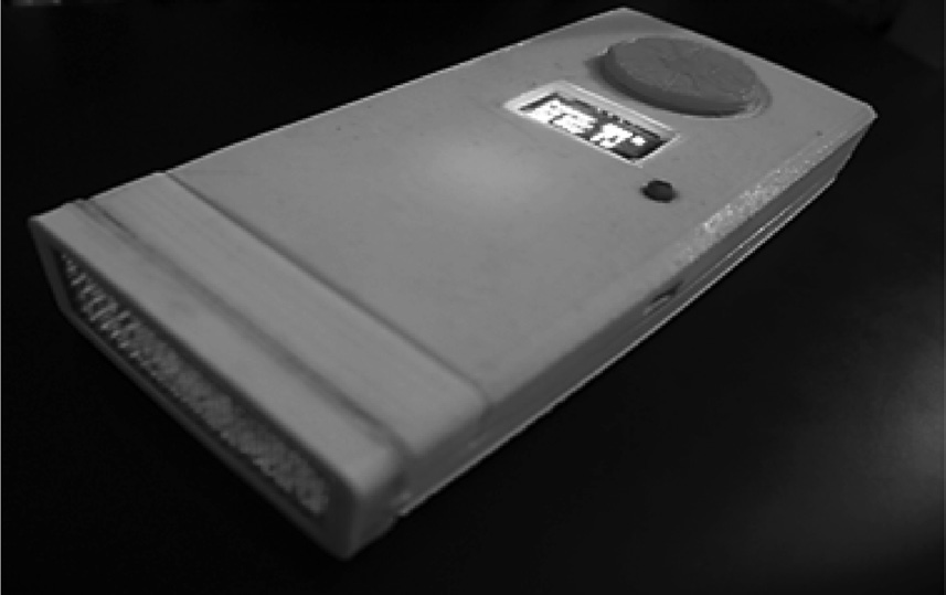
Figure 6. The prototype of the DBD plasma device.
Electrical properties
The prototype of the device produced a stable high-voltage output within a frequency range of 15 to 40 kHz. Raising the duty cycle increased the voltage until it reached its ‘saturated voltage amplitude’. Each frequency had a duty cycle where the output reached the saturated voltage amplitude, as shown in Figure 7. Lower frequencies tended to saturate sooner. For example, frequencies from 15 to 20 kHz reached saturation voltage at 20 % duty cycle, while frequencies from 25 to 35 kHz reached saturation voltage at 30 % duty cycle. Figure 8 presents the results of the voltage-current output and Lissajous figure for frequencies from 15 kHz to 35 kHz. The voltage amplitude (Vpp) reached its highest value at 15 kHz; it decreased with increasing frequency. Likewise, the mean-power consumption of the plasma reached its highest value (3.4 W) at 15 kHz and gradually reduced as the frequency increased. The electric currents recorded across the 100-Ω resistor did not exceed 50 mA. Due to the function of PWM, regulating the duty cycle modified the voltage amplitude. Figure 9 shows the results of various duty cycles at 25 kHz.
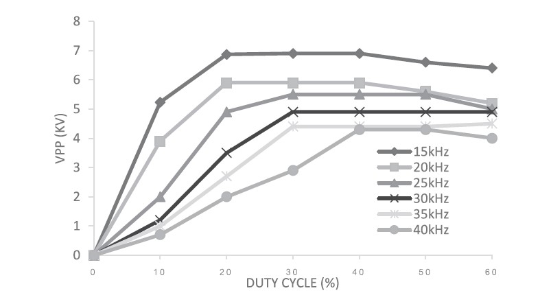
Figure 7. Changes of voltage amplitude at various frequencies when the duty cycle was varied from 0% to 60%.
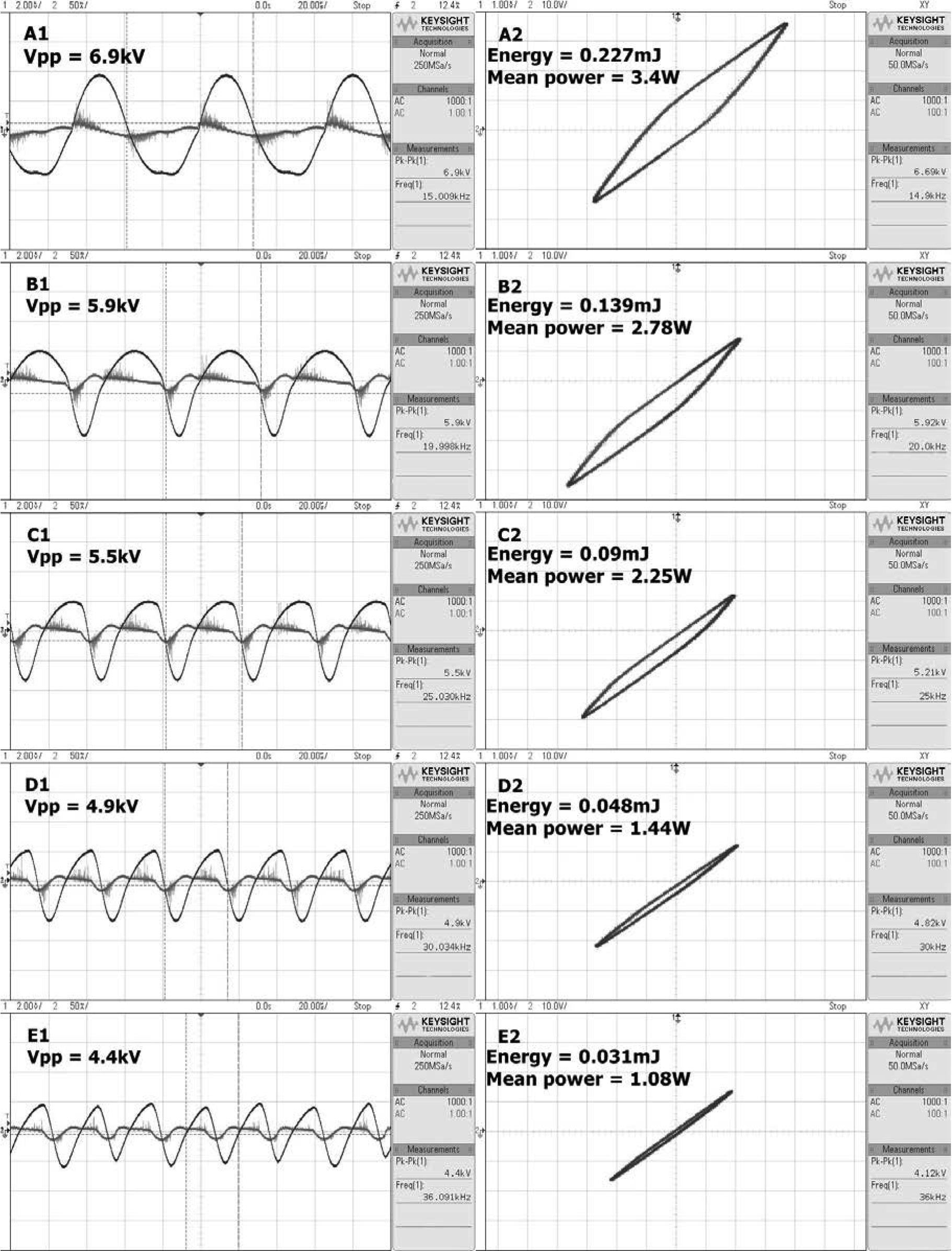
Figure 8. The results of maximum discharge at various frequencies: A (15 kHz), B (20 kHz), C (25 kHz), D (30 kHz), E (35 kHz); the relationship between voltage and current (left); the Lissajous figure (right).
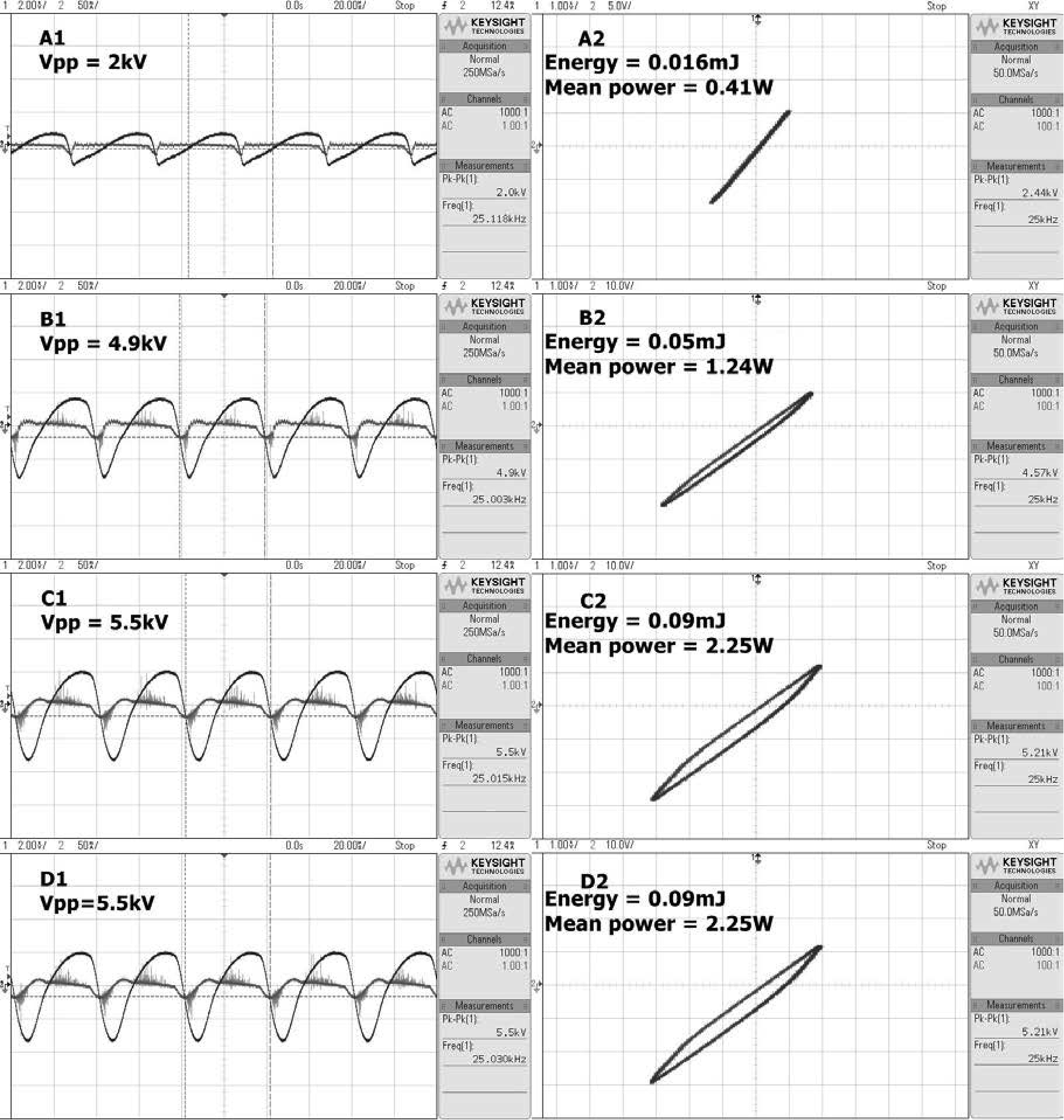
Figure 9. The results of discharge at 25 kHz with various duty cycles; A (10%), B (20%), C (30%), D (40%); the relationship between voltage and current (left); the Lissajous figure (right).
Plasma characteristics
As measured by OES, the studied device produced both reactive nitrogen species (N2, N2+) and reactive oxygen species (O, OH, O2- and O3) for wound treatment. While O and OH are seen in Figure 9, ozone (O3) is a product from the combination of a single O atom with an oxygen molecule (O2) (Misra et al., 2015). The line intensity of the 30-kHz OAS results was larger than that of 25 kHz. Similarly, at each frequency, higher duty cycles yielded the most significant results; hence, the darkest lines dominated the rest. The OES results of both 25 and 30 kHz showed fairly similar peaks, except an O (2s22p33p5P→2s22p33s5S) atom was observed at 777.4 nm at 25 kHz only.
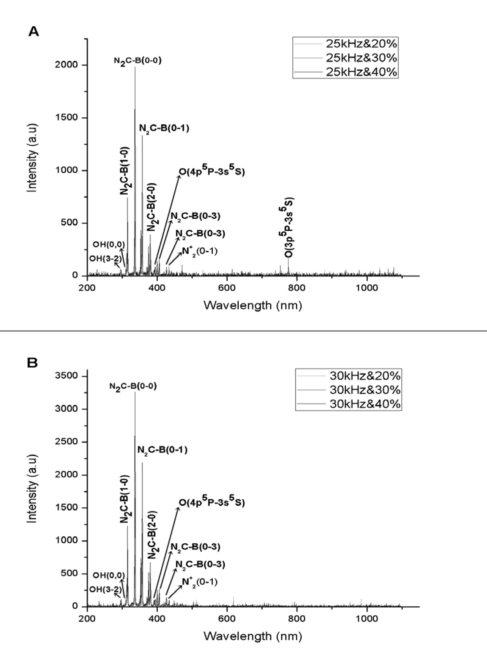
Figure 10. Optical emission spectrum of the DBD plasma discharge in air: A (25 kHz) and B (30 kHz).
DISCUSSION
The results demonstrated that the prototype device developed here could vary the frequency and duty cycle of electrical power to produce DBD plasma discharges; both influenced the voltage amplitude of the output, as shown in Figure 7. Thus, when the device was set to a specific frequency, the voltage amplitude could be varied by adjusting the duty cycle. To maximize device performance, the saturated voltage amplitude could be preset
at each frequency. Based on the voltage-current relationship in Figure 8, plasma discharge increased at higher frequencies (Dragonas et al., 2015). While the frequency influenced the number of plasma discharges, the voltage amplitude determined the level of energy per pulse. Similar to Jiang et al. (2013), the energy per pulse of the prototype, calculated from the Lissajous figure in Figures 8 and 9, was directly proportional to the applied voltage amplitude. More energy was injected into the gas to generate plasma discharge when a higher voltage amplitude was applied (Khatun et al., 2008). This induced a more uniform and intense surface discharge (Jiang et al., 2013). When the voltage amplitudes were the same, such as 4.9 kV at 25 and 30 kHz, more frequency-excitation created a larger mean-power (Khatun et al., 2009). Because of its variable power consumption, the device prototype was able to produce a variety of plasma discharge doses for different treatments (Chutsirimongkol et al., 2014). This is the first battery-operated plasma device capable of varying the plasma discharge.
The OES results demonstrated that regulating both voltage amplitude and frequency in the prototype device influenced plasma generation in ambient air. Although the OES measurements could not provide the concentration of reactive species, based on the line intensity and number of excited species (peak), they showed that the device efficiently produced active and excited particles (Chiper et al., 2004). The larger line intensity at 30 kHz than 25 kHz represented a more efficient production of plasma discharges; the frequency of the electrical field affected the number of plasma discharges, as well as the collisions between electrons and heavy particles, a key factor in ionization (Tendero et al., 2006). On the other hand, the amplitude of applied voltage influenced the electron temperature; this is a determinant affecting various heavy particles (Keida and Beilis, 2013). Thus, applied voltages with larger amplitudes increased the number of peaks in the OES results. This was seen in the OES results at 25 kHz, which had more peaks than 30 kHz, given its higher voltage amplitude.
The OES results proved that both reactive nitrogen species (N2, N2+) and reactive oxygen species (OH, O, O2-, O3) were found in the ambient plasma discharge of the prototype device. These activated species are crucial for wound healing (Emmert et al., 2013).
CONCLUSION
This study produced a prototype of a truly mobile and convenient battery-operated plasma device for first aid. By varying the power consumption of plasma discharge, the prototype potentially controlled the plasma treatment dose, making possible many kinds of applications in research and medical care. The OES results showed that the plasma discharge in ambient air produced activated species important to treating wounds and that this discharge could be regulated by adjustments of frequency and duty cycle.
ACKNOWLEDGEMENTS
The authors would like to thank Chiang Mai University for supporting this research −the ATMTech Research Center for providing the materials and the High Voltage Laboratory, Faculty of Engineering and BioPlasma Laboratory, Faculty of Science for providing the instruments.
REFERENCES
Barr, M. 2001. Introduction Width Modulation. Embedded Systems Programming. 14(10): 103-104.
Chiper, A.S., Aniţa, V., Agheorghiesei, C., Pohoaţa, V., Aniţa, M., and Popa, G. 2004. Spectroscopic diagnostics for a DBD plasma in He/Air and He/N2 gas mixtures. Plasma Processes And Polymers. 1(1): 57-62. https://doi.org/10.1002/ppap.200400003
Chutsirimongkol, C., Boonyawan, D., Polnikorn, N., Techawatthanawisan, W., and Kundilokchai, T. 2014. Non-Thermal plasma for acne and aesthetic skin improvement. Plasma Medicine. 4(1-4): 79-88. https://doi.org/10.1615/PlasmaMed.2014011952
Dragonas, F.A., Neretti, G., Sanjeevikumar, P., and Grandi, G. 2015. High-voltage high-frequency arbitrary waveform multilevel generator for DBD plasma actuators. IEEE Transactions on Industry Applications. 51(4): 3334-3342. https://doi.org/10.1109/ITA.2015.2409262
Emmert, S., Brehmer, F., Hanssle, H., Schon, M.P., Helmke, A., Mertens, N., Daschlein, G. 2013. Atmospheric pressure plasma in dermatology: Ulcus treatment and much more. Clinical Plasma Medicine. 1(1): 24-29. https://doi.org/10.1016/j.cpme.2012.11.002
Fridman, A., and Friedman, G. 2013. Plasma medicine – Drexel University, Philadelphia, PA, USA. p. 269, 304 – 312, 391 – 393.
Fridman, G., Peddinghaus, M., Balasubramanian, M., Ayan, H., Fridman, A., Gutsol, A., and Brooks, A. 2006. Blood coagulation and living tissue sterilization by floating-electrode dielectric barrier discharge in air. Plasma Chemistry and Plasma Processing. 26(4): 425-442. https://doi.org/10.1007/S11090-006-9024-4
Isbary, G., Stolz, W., Zimmermann, J.L., Shimizu, T., Li, Y.-F., Morfill, G.E., and Karrer, S. 2013. Non-thermal plasma-More than five years of clinical experience. Clinical Plasma Medicine. 1(1): 19-23. https://doi.org/10.1016/j.cpme.2012.11.001
Jiang, H., Shao, T., Zhang, C., Li, W., Yan, P., Che, X., and Schamiloglu, E. 2013. Experimental study of Q-V Lissajous figures in nanosecond-pulse surface discharges. IEEE Transactions on Dielectrics & Electrical Insulation. 20(4): 1101-1111. https://doi.org/10.1109/TDEI.2013.657.1423
Keida, M., and Beilis, I. 2013. Plasma engineering. Elsevier Inc. p. 83-126.
Kostov, K.G., Rocha, V., Koga-Ito, C.Y., Matos, B.M., Algatti, M.A., Honda, R.Y., and Mota, R.P. 2010. Bacterial sterilization by a dielectric barrier discharge (DBD) in air. Surface & Coatings Technology. 204(18): 2954-2959. https://doi.org/10.1016/j.surfcoat.2010.01.052
Khatun, H., Mishra, A., Kumar, M., Pal, U.N., Sharma, A. K., and Barhai, P. K. 2008. Study of filamentary behavior in coaxial dielectric barrier discharge lamp. Indian Journal of Pure & Applied Physics. 46: 889-892.
Li, Y.F., Zimmermann, J.L., and Morfill, G.E. 2012. Optimizing the distance for bacterial treatment using surface micro-discharge plasma. New Journal of Physics 14(2). https://doi.org/10.1088/1367-2630/14/2/023058
Lieberman, A.M., and Lichtenberg, J.A. 2015. Principle of plasma discharges and materials processing. p. 544-546.
Mahoney, J., Zhu, W., Johnson, V.S., Becker, K.H., and Lopez, J.L. 2010. Electrical and optical emission measurements of a capillary dielectric barrier discharge. The European Physical Journal D: Atomic, Molecular, Optical and Plasma Physics, 60(3): 441-447. https://doi.org/10.1140/epjd/e2010-00236-y
Marty, B. 1990. Practical switching power supply design. pp.119-125.
Misra, N.N., Keener, K.M., Bourke, P., and Cullen, P.J. 2015. Generation of in-package cold plasma and efficacy assessment using methylene blue. Plasma Chemistry And Plasma Processing, 35(6): 1043-1056. https://doi.org/10.1007/s11090-015-9638-5
Ni, Y., Lynch, M.J., Modic, M., Whalley, R.D., and Walsh, J. 2016. A solar powered handheld plasma source for microbial decontamination applications. Journal of Physics. D: Applied Physics. 49(35) Str. 355203-1-355203-8. https://doi.org/10.1088/0022-3727/49/35/355203
Pei, X., Liu, J., Xian, Y., and Lu, X. 2014. A battery-operated atmospheric-pressure plasma wand for biomedical applications. Journal of Physics: D Applied Physics. 47(14).
Priyadarshini, R. 2013. Atmospheric-pressure dielectric barrier discharge (DBD) in air: Plasma characterization for skin therapy. Thesis of Ruhr – University Bochum, p. 23-27.
Tendero, C., Tixier, C., Tristant, P., Desmaison, J., and Leprince, P. 2006. Atmospheric pressure plasmas: A review. Spectrochimica Acta Part B: Atomic Spectroscopy. 61(1): 2-30. https://doi.org/10.1016/j.sab.2005.10.003
Khoi Nguyen Ho1 and Anirut Chaijaruwanich2*
1 Biomedical Engineering Center, Faculty of Engineering, Chiang Mai University, Chiang Mai 50200, Thailand
2 Department of Industrial Engineering, Faculty of Engineering, Chiang Mai University, Chiang Mai 50200, Thailand
*Corresponding author. E-mail: anirut@eng.cmu.ac.th
Total Article Views