
Axial Response of Hemp-Fiber Composite Tube under Quasi-Static Compression and Impact Crushing. Paiboon Limpitipanich* and Anucha Promwungkwa
Published Date : 2019-08-23
DOI : https://doi.org/10.12982/CMUJNS.2019.0020
Journal Issues :
Number 3 , July-September 2019
ABSTRACT
Besides being eco-friendly, hemp fiber, a natural fiber, has a potential for use as fiber reinforcement for energy absorption structures. The advantage of the structure is to reduce the impact energy of a crash on the attached mem- ber or especially for occupants in an automotive body. In this study, the energy absorption capability and failure response of hemp fiber tubes were investigat- ed by applying an axial static compression and impact crushing. Three fiber volume fractions of hemp fiber tubes and epoxy resin tubes were studied. It was found that epoxy tube and hemp fiber tube with low fiber volume fraction behaves with a brittle failure mechanism, but progressive failure was found in tubes with high fiber content. Brittle failures let the member absorb less crushing energy, but progressive failures let high fiber tubes have high energy absorption. Progressive failure was found in high fiber tubes due to the tensile loading resistance of hemp fiber, especially that fiber aligned in the circum- ferential direction. For high volume content of 37.0%, the sample has a high specific energy absorption of 65.76 J/g, which is 20 times that of epoxy without reinforcing fiber. Low content of hemp fiber tube can be used as an energy absorbing structure for quasi-static axial compression, but high content of hemp fiber tubes are better in an impact crushing situation. It is hoped that synthetic fiber will be substituted by hemp fiber in some automotive applications.
Keywords: Hemp, Hemp composite, Energy absorption structure, Impact, Natural fiber
INTRODUCTION
Design of any vehicle structure must meet the crash energy management criteria in order to ensure an optimum collapse sequence during a crash (Thornton and Jeryan, 1988). The benefit is to reduce the impact energy of a crash on occupants. Various geometries of metal and composite materials such as circular, square and conical have been tested to evaluate their energy absorption capa- bility (Farley and Jones, 1989; Mamalis et al., 1997; Huang and Wang, 2009; Ataollahi et al., 2012; Tong et al., 2016; Yang et al., 2017). Composite materials reinforced by glass fiber and carbon fiber composites have been used in vehicle construction, because of their energy absorption potential which is compara- ble to that of metal structures (Ramakrishna, 1997). The other advantage is to reduce fuel consumption and exhaust emissions because of their light weight (Sapuan et al., 2005). They have been used as interior and exterior parts such as skin panels of hoods and doors, and load-bearing structures such as cross mem- bers and frame rails (Thornton and Jeryan, 1988; Holbery and Houston, 2006).
The collapse mechanism of a structure such as a tube can be identified into four modes, which are transverse shearing, brittle fracturing, lamina bending and local buckling (Farley and Jones, 1989; Mamalis et al., 1997). These modes can be summed up in two different failure modes, which are the catastrophic failure and the progressive failure (Garattoni, 2011). The progressive mode can be classified into two categories, i.e. splaying mode and fragmentation mode (Hull, 1991). For composite materials, catastrophic failure results from unstable inter-laminar or intra-laminar and circumferential crack growth. This failure mode allows a low energy absorption capability. The progressive mode occurs when a trigger is pro- vided at one end of the structure that introduces a high energy absorption capability.
Besides being eco-friendly, natural fibers are used as a reinforcing ma-terial for polymers. In contrast to synthetic fibers, natural fibers need lower pro- cessing energy and have energy and carbon-credit recoveries at the end of their life (Joshi et al., 2004; Dittenber and GangaRao, 2012). Hemp is one of the well- known natural fibers. Previous research has shown that hemp fiber composite has good strength (Yuanjian and Isaac, 2007; De Rosa et al., 2012; Meredith et al., 2012; Singh et al., 2014; Haghighatnia et al., 2017; Sullins et al., 2017). Yuanjian and Isaac (2007), for example, reported that hemp fiber reinforced polyester com- posite (with a fiber weight fraction of 44%) has strength and modulus of 53 MPa and 6.2 GPa, respectively. They are equivalent to those of four layers of ±45° glass fiber reinforced polyester composite with fiber weight fraction of 42%.
Hemp fiber has a potential for use as fiber reinforcement for energy ab- sorbing structures (De Rosa et al., 2012; Meredith et al., 2012). Meredith et al. (2012) tested the impact on conical specimens of jute, flax and hemp. The specimens were manufactured using vacuum assisted resin transfer mold- ing. They found that unwoven hemp exhibits high specific energy absorption of 54.3 J/g, which is comparable to that of carbon fiber polymeric composite.
This study investigated the axial response of hemp fiber tubes with three fiber volume fractions and conditions of axial compression which were quasi-static and impact crushing. Variation in specific energy absorption of epoxy and hemp fiber tubes under quasi-static compression and impact crushing were evaluated and compared. The effects of volume fraction of hemp fiber were examined. The failure mechanisms that made differences in energy absorption of the tube either under quasi-static compression or impact crushing are explained. A bevel trigger was produced at the top end of the tube to control the position of failure initiation.
MATERIALS AND METHODS
Materials
Nonwoven hemp mats of 600 g/m2 from HempFlax BV, Netherland were used in this study. Its tensile strength and Young’s modulus are 446.75±184.36 MPa and 18.23±8.26 GPa, respectively (Limpitipanich and Promwungkwa, 2014). Hemp mat was washed with reverse osmosis water to remove dust and contami- nants. It was dried at room temperature before being kept in an oven at 80°C for 24 hours. To reduce the thickness of the hemp mat, a roller machine was used to compress the mat from a thickness of 3 mm to about 0.7 to 0.8 mm before molding.
The density of the hemp mat after drying was measured accord-ing to ASTM D3800 with the Buoyancy (Archimedes) Method. The method is recommended for the density measurement of natural fiber (Truong et al., 2009). The measured density of the hemp mat is 1,356 kg/m3.
Hemp-fiber composite tube was fabricated using the vacuum assisted resin transfer molding technique at a lab scale. The material was molded in a gap between two 3-mm thick acrylic tubes. One acrylic tube had inside diameter of 19 mm and the other had outside diameter of 15 mm. The tubes were 200 mm in length. Next, rolled hemp was inserted in the 2-mm gap of the acrylic mold. To maintain concentricity between the two acrylic molds, plastic rings having constant width of 2 mm were inserted at both ends.
Epotec YD535LV/TH7257 (low viscosity epoxy from Aditya Birla Chem-icals (Thailand) Co., Ltd.) with density of 996 kg/m3 was used as the matrix of the hemp fiber composite. The epoxy has a 3 – 4 hours work life that guarantees fast and complete impregnation of reinforcing fibers and allows laminates to be produced by vacuum assisted resin transfer molding. The molding was cured at room temperature for 24 hours before it was post cured in an oven at 80°C. The curing time condition is recommended by Aditya Birla Chemicals (Thailand) Co., Ltd. as shown in the datasheet of Epotec YD535LV/TH 7253–8 (Epoxy Division, 2006).
After post curing, the tubes were cut to lengths of 60 mm for axial loading test. To reduce the initial peak load, a lathe was used to machine a 45° bevel trigger at one end of the specimens. The trigger is not only used for controlling the posi- tion of crushing initiation, but also for reducing the initial peak load and increas- ing the stability of the axial crushing process (Mamalis et al., 1997). Epoxy tubes and hemp fiber tubes with three fiber volume fractions of 9.3%, 19.3% and 37.0% were produced. A hemp fiber tube with no voids is assumed in this study. The volume fraction of the hemp fiber tube was calculated using equation 1:

where ρ is the density, m is the mass and the subscripts r and f are the properties of resin and fiber, respectively.
Compression test
Quasi-static compression test. The tube specimens were axially com- pressed between the platens of a 10 kN UTM machine (MTS model Sintech 2/S). The bottom end of the tube was fixed into a 5-mm deep hole, and then it was in- serted between the two compression plates of the UTM machine. The specimen was axially compressed to 35 mm distance with a constant crosshead speed of 1.25 mm/min. Load and displacement responses were recorded throughout the test. Five specimens for epoxy and the three volume fractions of hemp fiber specimens were tested.
Impact crushing test. The axial impact crushing test was conducted using a drop-weight impact tester. The capacity of the machine is 234 J. The bottom end of the tube was fixed in a 5-mm deep hole. Then, the impactor with a mass of 18.22 kg was released from a desired height to cause axial crushing to the specimen. Variation in impact energy can be made by changing the ini- tial height of the impactor. The initial height for each specimen type was var- ied due to the energy that could be absorbed by the specimen. Impact crushing load was measured by a 20 kN loadcell and recorded by National Instrument cDAQ-9172 at 10 kHz. A high speed video camera with 1,200 frames per sec- ond was used to record the impact test. Five specimens for epoxy tubes and three volume fractions of hemp fiber tubes were tested. The impact velocity was computed by the initial height of the impactor using equation 2 (Messiry, 2013):

where g is the acceleration due to gravity which is 9.81 m/s2, and h is the initial height of the impactor.
Energy absorption capability
The ability of structures that carry static compression and impact loads can be described by specific energy absorption using equation 3. For the static compression test, the absorbed energy can be calculated using equation 4 from the area under the load and displacement response. For the impact crushing test, the corresponding impact displacement was evaluated using equation 5, which was derived from the equations for impulse and momentum.

where mloss is the mass loss of the tube, F is the compressive load or crushing force, ᵟ is the compressive displacement, mimpactor is the mass of the impactor, and t is the time duration of crushing.
RESULTS
Quasi-static compression
The compressive load-displacement responses and the corresponding energy absorptions of epoxy and hemp-fiber specimens are plotted in Figure 1. At the beginning, the load was sharply increased due to the axial strain resistance of the tube. Then, the load was slowly raised before reaching the initial peak load. At this point, the bevel trigger at the top end was progressively crushed in the axial direction which let the load decrease. Next, the load gradually increased and dropped again due to the failure mechanism of the tubes. The load increased and dropped in this pattern throughout the test. For epoxy, the failure behavior was brittle fracture that results in catastrophic failure. Its surface was broken and the test never reached 35 mm in compressive displace- ment, as shown by the load-displacement curve in Figure 1(a) and by the bro- ken specimen in Figure 2(a). The maximum compressive displacement of the epoxy tube was 24.4 mm, while the minimum was 3.9 mm. For hemp fiber specimens, the bevel trigger was crushed to failure as shown in Figures 2(b) to (d) at compressive displacements of 3 mm, 5 mm and 10 mm, respective- ly. Next, axial delamination was found and growth in the axial direction, fol- lowed by bending of the tube surface, which is called frond bending as shown in, for example, Figure 2 (b) at compressive displacement of 6 mm and 18 mm. The hemp fiber specimen after complete compression also showed progres- sive failure. This failure behavior can absorb high energy during compression.
Figure 1 also presents the variation in specific energy absorption along the compressive displacement using equation 3. It was found that the epoxy specimen cannot absorb the compressive energy throughout its length because of its cata- strophic failure, especially for specimen no. 2. The hemp fiber specimen can ab- sorb higher energy and longer displacement than epoxy. At 35-mm displacement, the average specific energy absorption of epoxy was 9.95 J/g, and for 9.3%, 19.3% and 37.0% hemp fiber tubes it was 34.09 J/g, 37.06 J/g and 39.73 J/g, respectively.
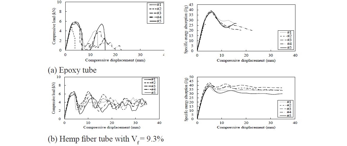
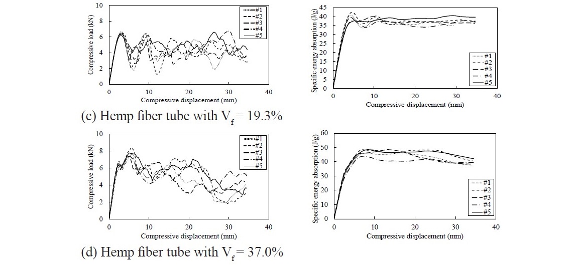
Figure 1. Variation in compressive load and specific energy absorption with applied compressive displacement under quasi-static test.
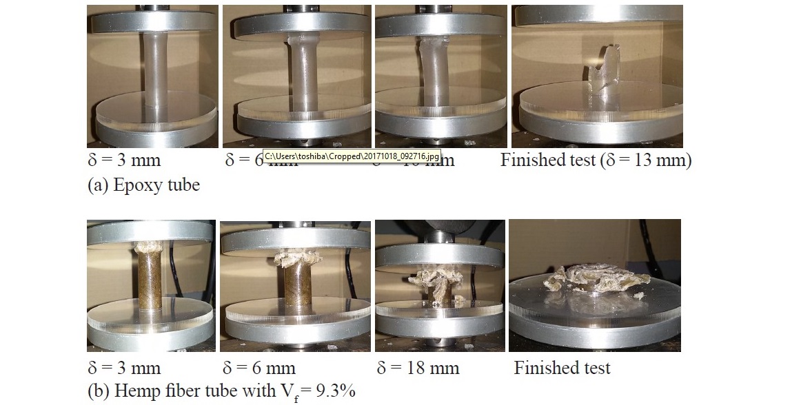
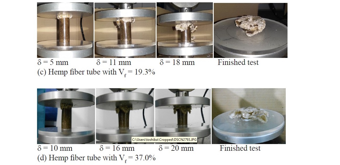
Figure 2. Failure mechanism of epoxy and hemp fiber tubes at different compressive displacements.
Impact crushing
Crushing load and time response and finished test specimen of epoxy and hemp fiber are shown in Figure 3. The epoxy tube provided low crush- ing load with short crushing time response. The load sharply increased, and then it decreased due to the total failure of the specimen. Only one loop of load and time response was found for the epoxy tube and the catastrophic mode was found as shown in Figure 3 (a) in the specimen after finishing the test. For hemp fiber tubes with fiber volume fraction of 9.3% and 19.3% (see Figures 3 (b) to (c)), the load was increased and decreased due to specimen failure throughout the test. A combination of brittle and progressive failures was also found as shown. For high content of hemp fiber at 37.0% fiber content, the load sharply increased to around 7.5 kN to 8.5 kN, and then it decreased due to failure of the specimen. It can be seen in Figure 3 (d) that the specimen did not totally fail even at the highest capacity of 234 J of the impact tester.
Figure 4 presents the failure of epoxy and hemp fiber tubes at different impact crushing times. The epoxy specimen was brittle and failed totally before 10 ms of crushing time. For hemp fiber tube with fiber volume fractions of 9.3% and 19.3%, the trigger was either broken or degraded progressively as shown at times 5 ms and 10 ms. The specimen with high fiber content of 37.0% presented progressive failure at times of 2.5 ms, 5 ms, 10 ms and 20 ms. It was also found that after the test, at time 20 ms, the specimen was not totally collapsed.
Details of impact test and evaluation of result are listed in Table 1. The initial height of the impactor was varied for epoxy and hemp fiber specimens in order to make a variation in crushing energy to the tube. All 60-mm long epoxy specimens failed at impact velocity between 1.55 m/s and 2.32 m/s. Their specific energy absorptions were 2.47 J/g and 3.76 J/g. For hemp fiber samples, the ini- tial height of the impactor was higher than when testing epoxy. This corresponds to the crushing impact energy that the specimen can absorb. Hemp fiber tubes with fiber content of 9.3% behaved catastrophically and progressively in com- bination. They were totally collapsed by an impact velocity between 2.47 m/s and 3.32 m/s, and their specific energy absorption was between 10.00 J/g and 13.89 J/g. Higher content of hemp fiber lets the tube be more ductile. Specific energy absorption between 29.17 J/g and 36.76 J/g was seen when impacting the 19.3% fiber specimen with a speed between 3.87 m/s and 4.56 m/s. High crush- ing energy between 61.19 J/g and 69.82 J/g can be absorbed by 37.0 % content of hemp fiber with an impactor speed between 4.34 m/s and 4.80 m/s. The aver- age specific energy absorptions of epoxy tube, and 9.3%, 19.3 %, 37.0% hemp content tubes were 3.07 J/g, 11.91 J/g, 33.47 J/g and 65.76 J/g, respectively.
The absorbed energy presented in Table 1 was calculated from the crush- ing load and time responses using equations 3 to 5. Since the area under the curve is the deviation in velocity of the impactor, the crushing displacement can be evaluated using the equation of impulse and momentum as in equation 5. Figure 5 presents the crushing load and the corresponding displacement of epoxy and hemp fiber specimens. It can be seen that the crushing load initially increased and then decreased due to failure and may increase and decrease again before it diminishes. It is noted that, for example, the drop weight energy of the impactor for a hemp fiber specimen with fiber volume fraction of 19.3% at the height of impactor of 0.96 m is 171.95 J, and the absorbed energy or corresponding area under the calculated load-displacement curve is 168.48 J. Therefore, it can be noted confidently that the area under the crushing load and the time response can correctly estimate the absorbed energy of the sample using equations 3 to 5.
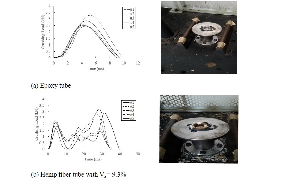
Figure 3. Impact crushing load-time response and failure behavior of epoxy and hemp-fiber tubes.
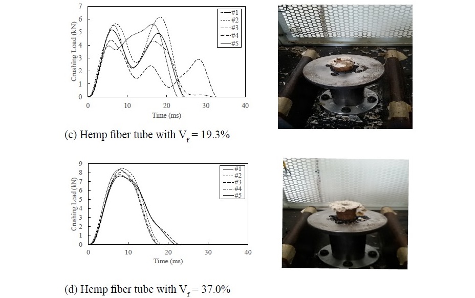
Figure 3. Continued.
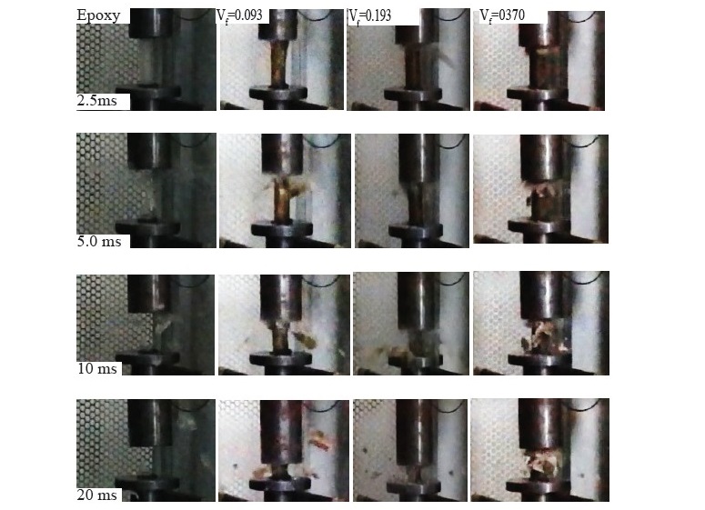
Figure 4. Comparison of epoxy and hemp fiber specimens at different impact crushing times.
Table 1. Test data for impact crushing and analysis results.
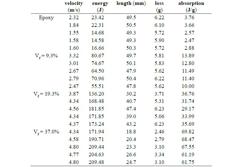
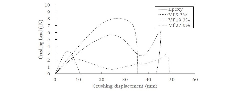
Figure 5. Crushing load and displacement responses evaluated by equation 5.
Figure 6 presents the correlation of specific energy absorption and fiber volume fraction. High fiber volume fraction results in high specific energy absorption as found in static compression. It can be seen in the chart that linear correlation of fiber content and specific energy absorption can be observed as reported by Meredith et al. (2012). Composites with higher volume fraction have less epoxy available, which reduces the energy dissipation due to epoxy cracking (Meredith et al., 2012).
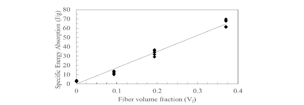
Figure 6. Variation in fiber volume fraction and specific energy absorption under impact crushing.
Comparison of behavior under quasi-static compression and impact crushing
The load and displacement responses of the tubes under quasi-static and impact crushing are of the same pattern. The load increased to reach the initial peak load and then decreased. Then, the load was increased and dropped accord- ing to the failure mechanism of the tubes, and stayed in this pattern throughout the test. In this study, it can be seen that the load fluctuations of tubes under quasi-static test were larger than those of impact crushing tested tubes. It is not- ed that the fluctuation of load under static compression are in the same pat- tern as in the static tests by Mamalis et al. (1997) and Meredith et al. (2012).
The failure patterns of hemp fiber tubes under quasi-static and impact crushing are significantly different. Failure of tubes under quasi-static compres- sion and impact crushing are compared and presented in Figure 7. Brittle frac- ture can be found in the epoxy tube (see Figure 7(a)), even with quasi-static compression or impact crushing. The tubes collapsed with catastrophic failure. For low reinforcement fiber tubes at 9.3% and 19.3%, the sample showed that a progressive failure in combination of splaying and fragmentation modes can be found under quasi-static test, as seen in the left of Figure 7(b) and Figure 7(c). However, tubes behaved with less ductility with a combination of brit- tle and ductile surfaces, even when using a low velocity of the impactor. For a high fiber volume fraction of 37.0%, the failure surface of hemp fiber tube under impact crushing, as shown in the right of Figure 7(d), revealed the splay- ing mode of progressive failure; an axial crack grows in the middle of the tube surface and its lamina bends inside and outside. This failure pattern is clearly seen in the tube under quasi-static compression, while the specific energy absorption under impact test was much higher than that under quasi-static test.
Figure 8 presents the comparison of the specific energy absorption of epoxy and hemp fiber tubes under quasi-static compression and impact crushing. It can be seen that the specific energy absorption for 9.3%, 19.3% and 37.0% hemp fiber tubes under quasi-static test were 34.09 J/g, 37.06 J/g and 39.73 J/g, while those of hemp fiber tubes under impact crushing were 11.91 J/g, 33.47 J/g and 65.76 J/g, respectively. With 9.3% of fiber content, the tube under very low speed compression presented 3 times higher specific energy absorption than that of the tubes under impact crushing. For 19.3% hemp fiber tubes, the specific energy absorptions under both loadings are in agreement. At high fiber volume fraction of 37.0%, the specific energy absorption of the tube under impact crush- ing is much higher than that of the tube under quasi-static compression. Due to the speed of compression, Figure 8 also shows less variation in fiber volume fraction of hemp fiber tube and specific energy absorption under quasi-static compression. For impact crushing, a higher variation in fiber volume fraction and specific energy absorption is presented. The reason is that, under quasi-static compression, a progressive failure can be found even using composites with low fiber volume fraction, but under impact crushing, low fiber content made the tube collapse by a combination of catastrophic failure and progressive failure.
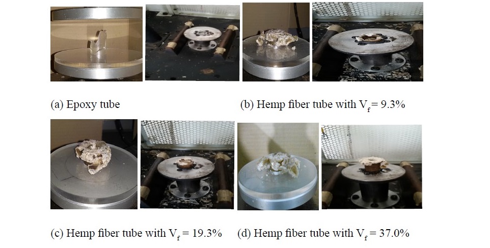
Figure 7. Comparison of failure behavior under quasi-static compression (left) and impact crushing (right).
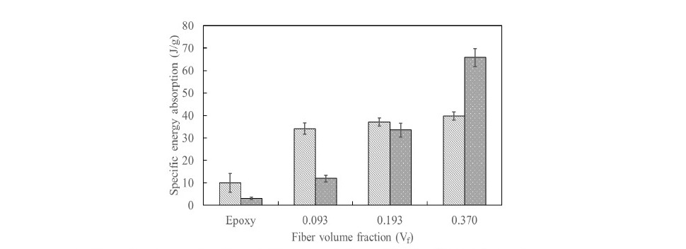
Figure 8. Comparison in specific energy absorption under quasi-static compression and impact crushing, error bars at ±1 SD.
DISCUSSION
This study attempted to measure the energy absorption capability and in- vestigated the failure behavior of epoxy and hemp fiber tubes. Variation of fiber volume fraction was produced using vacuum assisted resin transfer molding. The energy absorption capabilities of epoxy and hemp fiber tubes were presented by specific energy absorption. A bevel trigger of 45° was produced at the top end of the sample for controlling the position of failure initiation. Not only did the trigger make failure stability by controlling the initial position of failure, but it also allowed the member to absorb high crushing energy (Mamalis et al., 1997).
Under a quasi-static test, the epoxy tube behaved in a brittle way with catastrophic failure. It could not absorb energy throughout its length. With very low speed of compression, the sample with hemp fiber showed that a progressive failure can be found even using composites with low fiber volume fraction of 9.3%. Progressive failure lets the tube absorb energy throughout its length. Then, for quasi-static compression, the tubes have the opportunity to be used as energy absorption structures even using low hemp content. The failure mechanisms of hemp fiber tubes are axial crack growth and frond bending. The compressive energy was dissipated due to frond bend- ing, axial crack growth and friction between frond/frond and frond/platen.
For impact crushing, epoxy and low fiber content samples presented cat- astrophic failure. Less impact energy could be absorbed by these specimens even under low velocity impact. Reinforcement with low fiber content made the tube collapse by a combination of catastrophic and progressive failures. Higher fiber content made the member behave in a more ductile way and then have high en- ergy absorption capability. For 37.0% fiber content, the highest content that was used in this study, high average crushing energy of 65.76 J/g could be absorbed.
Fiber volume content was a significantly effect on the specific energy absorption. High fiber volume fraction results in high specific energy absorption of structure either under applying quasi-static compression or impact crushing. The 37.0% fiber content tube had the average specific energy absorption of 65.76 J/g, which is 20 times higher than that of epoxy without reinforced fiber. It was higher than that of 54.3 J/g which was tested by Meredith et al. (2012) with a conical hemp-fiber specimen.
Failure behaviors of hemp fiber tube under quasi-static and impact crush- ing were significantly different. Quasi-static compression on low hemp fiber content specimens showed that the specimen behaved with more ductility, but for axial crushing, even using a low velocity of the impactor, the specimen behaved with less ductility. The patterns for the load and displacement responses of quasi- static compression and impact crushing were also different according to the
failure behaviors. Thus, tubes with low hemp fiber content have the opportunity to be used as an energy absorption structure for quasi-static axial compression, but high hemp fiber content tubes must be better in an impact crushing situation.
Other parameters of structure, such as noncircular geometry, natural braid and aligned fibers, should be further studied to evaluate the specific energy absorption. Other energy absorption capability, such as initial crushing load, mean crushing load and crash force efficiency, should be further compared for using different parameters. High specific energy absorption of hemp fiber tube showed that hemp fiber has a potential for use as the fiber reinforcement of energy absorbing structures.
ACKNOWLEDGEMENTS
This research was supported by the first author’s Ph.D. scholarship, Burapha University. The authors thank the Department of Aerospace Engineering, Kasetsart University for providing the drop-weight impact tester.
REFERENCES
Ataollahi, S., Taher, S.T., Eshkoor, R.A., Ariffin, A.K., and Azhari, C.H. 2012. Energy absorption and failure response of silk/epoxy composite square tubes: Experimental. Composites Part B: Engineering. 43(2): 542-548. https://doi.org/10.1016/j.compositesb.2011.08.019
De Rosa, I.M., Dhakal, H.N., Santulli, C., Sarasini, F., and Zhang, Z.Y. 2012. Post-impact static and cyclic flexural characterisation of hemp fibre re- inforced laminates. Composites Part B: Engineering. 43(3): 1382-1396. https://doi.org/10.1016/j.compositesb.2011.09.012
Dittenber, D.B., and GangaRao, H.V.S. 2012. Critical review of recent publica- tions on the use of natural composites in infrastructure. Composites Part A: Applied Science and Manufacturing. 43(8): 1419-1429. https://doi. org/10.1016/j.compositesa.2011.11.019
Epoxy Division. 2006. Technical data sheet EPOTEC YD 535 LV/TH 7253-8.
Aditya Birla Chemicals (Thailand) Ltd., Bangkok, Thailand.
Farley, G.L., and Jones, R.M. 1989. Energy-absorption capability of composite tubes and beams. NASA TM 101634. National Aeronautics and Space Administration, Hampton, Virginia, USA.
Garattoni, F. 2011. Crashworthiness and composite materials: Development of an experimental test method for the energy absorption determination and implementation of the relative numerical model [dissertation]. University of Bologna, Forl`I, Italy.
Haghighatnia, T., Abbasian, A., and Morshedian, J. 2017. Hemp fiber reinforced thermoplastic polyurethane composite: An investigation in mechanical properties. Industrial Crops and Products. 108: 853-863. https://doi. org/10.1016/j.indcrop.2017.07.020
Holbery, J., and Houston, D. 2006. Natural-fiber-reinforced polymer composites in automotive applications. Journal of the Minerals, Metals and Material Society. 58(11): 80-86. https://doi.org/10.1007/s11837-006-0234-2
Huang, J., and Wang, X. 2009. Numerical and experimental investigations on the axial crushing response of composite tubes. Composite Structures. 91(2): 222-228. https://doi.org/10.1016/j.compstruct.2009.05.006
Hull, D. 1991. A unified approach to progressive crushing of fibre-reinforced composite tubes. Composites Science and Technology. 40(4): 377-421. https://doi.org/10.1016/0266-3538(91)90031-J
Joshi, S.V., Drzal, L.T., Mohanty, A.K., and Arora, S. 2004. Are natural fiber composites environmentally superior to glass fiber reinforced compos- ites? Composites Part A: Applied Science and Manufacturing. 35(3): 371-376. https://doi.org/10.1016/j.compositesa.2003.09.016
Limpitipanich, P., and Promwungkwa, A. 2014. Determination of tensile properties of hemp-fiber bundle by using tensile testing equipment with raspberry pi. Advanced Materials Research. 931-932: 1308- 1312. https://doi.org/10.4028/www.scientific.net/AMR.931-932.1308
Mamalis, A.G., Manolakos, D.E., Demosthenous, G.A., and Ioannidis, M.B. 1997. The static and dynamic axial crumbling of thin-walled fibreglass composite square tubes. Composites Part B: Engineering. 28(4): 439- 451. https://doi.org/10.1016/S1359-8368(96)00066-2
Meredith, J., Ebsworth, R., Coles, S.R., Wood, B.M., and Kirwan, K. 2012. Nat- ural fibre composite energy absorption structures. Composites Science and Technology. 72(2): 211-217. https://doi.org/10.1016/j.compscitech.2011.11.004
Messiry, M.EI. 2013. Theoretical analysis of natural fiber volume fraction of reinforced composites. Alexandria Engineering Journal. 52(3): 301-306. https://doi.org/10.1016/j.aej.2013.01.006
Ramakrishna, S. 1997. Microstructural design of composite materials for crash- worthy structural applications. Materials and Designs. 18(3): 167-173. https://doi.org/10.1016/S0261-3069(97)00098-8
Sapuan, S.M., Maleque, M.A., Hameedullah, M., Suddin, M.N., and Ismail, N. 2005. A note on the conceptual design of polymeric composite automo- tive bumper system. Journal of Materials Processing Technology. 159(2): 145-151. https://doi.org/10.1016/j.jmatprotec.2004.01.063
Singh, S., Deepak, D., Aggarwal, L., and Gupta, V.K. 2014. Tensile and flex- ural behavior of hemp fiber reinforced virgin-recycled HDPE matrix composites. Procedia Materials Science. 6: 1696-1702. https://doi.org/ 10.1016/j.mspro.2014.07.155
Sullins, T., Pillay, S., Komus, A., and Ning, H. 2017. Hemp fiber reinforced polypropylene composites: The effects of material treatments. Compoites Part B: Engineering. 114: 15-22. https://doi.org/10.1016/j.compositesb.2017.02.001
Thornton, P.H., and Jeryan, R.A. 1988. Crash energy management in composite automotive structures. International Journal of Impact Engineering. 7(2): 167-180. https://doi.org/10.1016/0734-743X(88)90024-3
Tong, Y., Xu, Y., Wang, J., and Suman, B. 2016. Energy absorption capability of carbon fiber reinforced plastic tubes with semi-circle grooved external trigger. Journal of Reinforced Plastics and Composites. 35(20): 1460- 1476. https://doi.org/10.1177/0731684416654579
Truong, M., Zhong, W., Boyko, S., and Alcock, M. 2009. A comparative study on natural fibre density measurement. The Journal of the Textile Institute. 100(6): 525-529. https://doi.org/10.1080/00405000801997595
Yang, Y., Ma, Y., Xu J., and Hamada, H. 2017. Energy absorption capability of hybrid fibers reinforced composite tubes. In Kaneko S. et al., editors. Carbon-related materials in recognition of Nobel lectures by Prof. Akira Suzuki in ICCE. Springer, Cham. p.145-173.
Yuanjian, T., and Isaac, D.H. 2007. Impact and fatigue behaviour of hemp fiber composites. Composites Science and Technology. 67(15-16): 3300-3307. https://doi.org/10.1016/j.compscitech.2007.03.039
Paiboon Limpitipanich1,2* and Anucha Promwungkwa1
1Department of Mechanical Engineering, Faculty of Engineering, Chiang Mai University, Chiang Mai 50200, Thailand
2Department of Mechanical Engineering, Faculty of Engineering, Burapha University, Chonburi 20131, Thailand
*Corresponding author. E-mail: paiboonl@eng.buu.ac.th
Total Article Views
Article history:
Received: May 30, 2018;
Revised: October 8, 2018;
Accepted: November 16, 2018

